
This article was automatically translated from Japanese using AI. The Japanese version is the authoritative version.
What is PWM output?
PWM stands for pulse width modulation. It is a method of modulating a signal by changing the duty cycle of the waveform.
For details, see my previous post.
PWM output on Arduino
The Arduino UNO uses a Microchip microcontroller called the ATmega328 as its main chip.
Once you start digging deep into Arduino programming, you inevitably end up having to read the microcontroller’s datasheet, so it is worth taking a look at least once. (Which is exactly the situation I’m in now.)
The Arduino has three timers (Timer/Counter).
These timers govern timing in Arduino programs.
Functions such as delay() and tone() rely on them for their measurements.
| Timer/Counter | Pin number | Bit width | Role | PWM frequency |
| Timer0 | 5, 6 | 8 bit | Manages Arduino timing delay(), millis(), micros(), etc. | 977 Hz |
| Timer1 | 9, 10 | 16 bit | Servo library, etc. | 490 Hz |
| TImer2 | 3, 11 | 8 bit | tone(), etc. | 490 Hz |
This time we will change the PWM output frequency by manipulating these timers.
Incidentally, since this alters the timers at their core, you might also be able to tweak functions like delay() in useful ways. (Though it seems more likely that they would simply be thrown off and behave erratically.)
Because TImer0 generally affects the system as a whole, I recommend using TImer1.
Useful references
https://playground.arduino.cc/Main/TimerPWMCheatsheet/
https://www.arduino.cc/en/Tutorial/SecretsOfArduinoPWM
https://atooshi-note.com/arduino-1hz-pwm/
http://blog.kts.jp.net/arduino-pwm-change-freq/
http://garretlab.web.fc2.com/arduino/inside/hardware/arduino/avr/cores/arduino/wiring_analog.c/analogWrite.html
Overview of the program
The overall approach is to change the Arduino timer’s register settings so that the PWM output frequency can be set freely.
The goal is to be able to output low frequencies, so the program is written to produce 10 Hz.
Here I connect an LED to pin 10 and write a program that lets you freely change the frequency and duty cycle of its blinking.
Since we are using pin 10, we work with TImer1.
Program code
//レジスタの設定を変えるためのもの
#include <avr/io.h>
int PWMPin = 10;

//関数の定義
//frq:周波数 (1Hz~指定できる)
//duty:指定したいduty比
void HzWrite(int frq, float duty) {

    // モード指定
  TCCR1A = 0b00100001;
  TCCR1B = 0b00010100; //分周比256を用いる

  // TOP値指定
  OCR1A = (unsigned int)(31250 / frq);

  // Duty比指定
  OCR1B = (unsigned int)(31250 / frq * duty);
}


void setup() {
  pinMode(PWMPin, OUTPUT);
}

void loop() {
  HzWrite(10, 0.5);
  delay(5000);
  digitalWrite(PWMPin, LOW);
  delay(5000);

}
Explanation of the program
First, include <avr/io.h> in order to change the register settings.
#include <avr/io.h>Next, to build a function that works together with delay() to repeat a 10 Hz output every five seconds, we define a function called HzWrite. Its arguments allow you to specify the frequency and duty cycle.
void HzWrite(int frq, float duty) {

}
Next comes setting the mode.
The registers used here are TCCR1A/TCCR1B. (TCCR: Timer/Counter Control Register)
The “1” indicates TImer1; if you want to use Timer2, use TCCR2A/TCCR2B instead.
To set the PWM frequency to a specific value in Hz, you need to specify the TOP value yourself.
The larger the TOP value, the lower the output frequency.
Here I use 10 Hz as an example. Since this is very slow compared with the 16 MHz system clock, a large TOP value and a large prescaler are required. For this reason, we use Timer1, which offers the largest range.
With the 8-bit Timer0 and Timer2, the maximum TOP value is 255 (2^8 – 1), while with the 16-bit Timer1 it is 65535 (2^16 – 1).
(The reason for the -1 is that the range is 0–255 or 0–65535: the number of values is 2^x, but the maximum value must be one less.)
In terms of how the system works, the counter increments up to the TOP value (counting 0, 1, 2, …), and when it matches OCRxA/OCRxB (where x is the timer number; each timer has two output pins, A and B, assigned to it), the pin output changes state (e.g., LOW→HIGH). Once the counter reaches the TOP value, it then decrements back down to 0 (counting down 65535, 65534, 65533, …), and just as during the increment phase, the pin output changes state when the count matches OCRxA/OCRxB.
On the Arduino UNO, the speed at which this counter increments can be changed to some extent by changing the prescaler setting. (“To some extent” means you can choose from 1/8/64/256/1024.)
The prescaler is the ratio (n) used when dividing the frequency (multiplying the frequency by 1/n).
In other words, dividing 1000 Hz by a prescaler of 10 gives 100 Hz.
Incidentally, with a prescaler of 1 the timer runs at 16 MHz, the system clock of the Arduino UNO (ATmega328).
In short, by changing the TOP value, the OCRxA/OCRxB values, and the prescaler, you can freely set the points at which the output switches.
Since we want 10 Hz here, we use a prescaler of 256 to leave plenty of margin.
On the Uno, the clock is 16 MHz, so one count takes 1 / 16 MHz = 62.5 ns (prescaler 1).
With a prescaler of 256, counting all the way to TOP takes 62.5 ns x 256 x 65535 = 1.04856 s, so frequencies as low as 1 Hz can be specified.
This program can generate frequencies from 1 Hz up to 31250 Hz.
However, as you approach 31250 Hz it becomes impossible to set the duty cycle precisely.
If you want fine control over the duty cycle, you can only go up to about 300 Hz.
By changing the prescaler setting in this program, you can build a version that produces the frequency range suited to your own application.
Next, we write what to set in TCCR1A/TCCR1B.
The fine details here are rather complicated, so let’s just work through the datasheet and set them roughly.
Here the values are given in binary, so they begin with 0b. In TCCR1A you set COM1A1, COM1A0, COM1B, unused, unused, WGM11, WGM10 to 1 or 0.
In TCCR1B you set unused (ICNC1), unused (ICES1), unused, WGM13, WGM12, CS12, CS11, CS10, respectively.


First, here we select Mode 9, whose PWM mode is Phase and Frequency Correct.
In this case the TOP value is set in OCR1A.
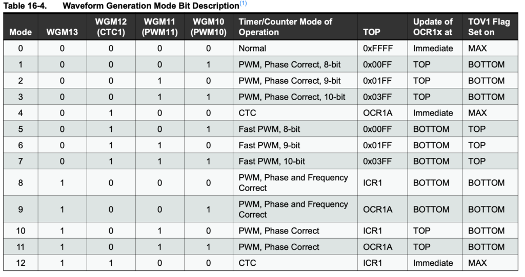
Therefore, WGM13 / WGM12 / WGM11 / WGM10 are 1, 0, 0, 1, respectively.
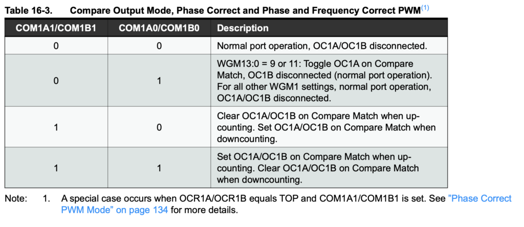
For COM1B1 / COM1B0: 0, 0 means no output; 0, 1 means toggle operation (the output is inverted on a compare match);
1, 0 outputs LOW while the counter is between OCR1A/B and TOP, and HIGH while it is between 0 and OCR1A/B;
1, 1 is the inverse of 1, 0.
Here, since we want to switch the output LED between LOW and HIGH to produce the frequency, we set COM1B1 / COM1B0 to 1, 0.
We choose 1, 0 because it makes the sketch easier to follow.
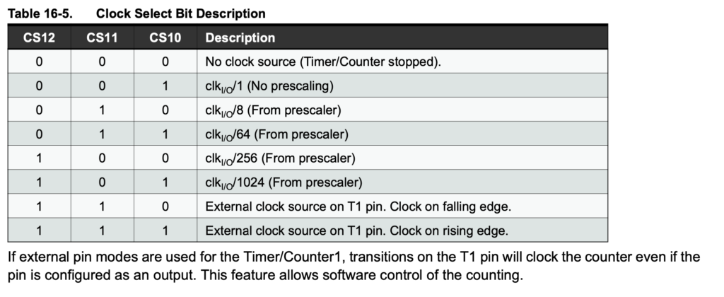
Since we are using a prescaler of 256 here, CS12/CS11/CS10 are set to 1, 0, 0.
To summarize, we get the following.
TCCR1A = 0b00100001;
TCCR1B = 0b00010010;
Next we set OCR1A and OCR1B so that the output is generated with the specified frequency and duty cycle.
  // TOP値指定
  OCR1A = (unsigned int)(31250 / frq);

  // Duty比指定
  OCR1B = (unsigned int)(31250 / frq * duty);
When using Phase and Frequency Correct PWM, the counter both increments and decrements, so the output frequency can be expressed as follows.
Frequency frq = IC clock frequency / (prescaler * TOP value * 2)
Conversely, to obtain the TOP value:
TOP value = IC clock frequency / (prescaler x frq x 2)
For the Arduino UNO with a prescaler of 256:
TOP value = OCR1A = 16,000,000 / (256 x frq x 2) = 31250 / frq
Since we want the timing at which LOW and HIGH switch to correspond to OCR1A/OCR1B = duty cycle,
OCR1B = 31250 / frq x duty
An unsigned int is used to prevent overflow.
Here is the main part of the output code.
void setup() {
  pinMode(PWMPin, OUTPUT);
}

void loop() {
  HzWrite(10, 0.5);
  delay(5000);
  digitalWrite(PWMPin, LOW);
  delay(5000);

}
PWMPin, i.e. pin 10, is set as OUTPUT, and the frequency and duty cycle are specified with HzWrite().
After waiting with delay(), the output is turned off with digitalWrite(PWMPin, LOW), followed by another delay().
That covers the full program and its explanation.
Afterword
When looking for blog posts on how to change the PWM output frequency, I found many more results by searching for AVR, ATmega328, or 328P than by searching for Arduino.
This post was only a rough overview, so if you want to dig deeper, I encourage you to look into it yourself.