Here are the slides from a talk I gave on how to use Git and GitHub.
The slides cover everything from hands-on operations in GitHub to the steps needed to make your program code available alongside a published paper.
Sharing paper data and analysis code is increasingly expected these days. Beyond that, managing code with GitHub has become an essential part of working on collaborative research.
[Updated January 15, 2024] https://www.slideshare.net/slideshow/embed_code/key/vzfmHD9i6I15wI
What gets downloaded is an app you can run as is, so just move it into the Applications folder on your Mac.
Switching VS Code to Japanese
Install the “Japanese Language Pack for Visual Studio Code”.
Select Extensions from the menu bar on the left and type “Japanese Language Pack for Visual Studio Code”.
Then install the package with that same name that appears at the top of the list.
After that, restart VS Code and check that the interface is now in Japanese.
Installing the Python extension
Next, install the Python extension in the same way.
Select Extensions from the menu bar on the left, type “Python,” and install Python.
This sets up a Python development environment: you can use Jupyter when writing Python programs in VS Code, and the syntax is automatically recognized and color-coded.
Checking that it actually works
Create a file called test.py in any directory you like.
Create a new file, choose a text file, and specify Python as the language.
Then name it test.py and enter the following program:
print(“Hello World!!”)
Type that in.
Then run it with the play button in the upper right.
Hello World!! will be printed in the terminal below. Once you get this far, your Python development environment is up and running.
If you have set up virtual environments with Anaconda, you can select the one you want from the Python interpreter selector in the lower right. Alternatively, you can activate a virtual environment with the conda command in the terminal.
Have you ever wanted to branch on multiple conditions with an if statement, tried using elif, and found that although no error was raised the results still weren’t right? If so, the situation described below might be what’s happening. I made this mistake myself, so I’m writing it down here for reference.
The problematic program
The problem arises when you write two conditions in the if and elif statements of a program that includes elif.
def trable(a, b):
    if a >= 10 & b >= 10:
        print("patern A")
    elif a >= 10 & b < 10:
        print("patern B")
    elif a < 10 & b >= 10:
        print("patern C")
    else:
        print("patern D")

trable(11, 11)
trable(11, 9)
trable(9, 11)
trable(9, 9)
When you run the program above, you might expect the cases to be sorted into patterns A, B, C, and D in order from the top, but what you actually get is the output below.
patern A
patern B
patern C
patern B
So what happens if we swap the order?
def trable(a, b):
    if a >= 10 & b >= 10:
        print("patern A")
    elif a < 10 & b < 10:
        print("patern B")
    elif a >= 10 & b >= 10:
        print("patern C")
    else:
        print("patern D")

trable(11, 11)
trable(9, 11)
trable(11, 9)
trable(9, 9)
If you swap the code for patterns B and C, expecting the output to come out as A, B, C, D, what you actually get is the output below.
patern A
patern D
patern D
patern D
elif itself is used as follows when you want to define multiple conditions.
if 条件式A:
  条件式Aが真(True)となった場合の処理
elif 条件式B:
  条件式Aが偽(False)で、条件式Bが真(True)となった場合の処理
else:
  条件式Aが偽(False)で、条件式Bも偽(False)となった場合の処理
However, once the conditional expressions in the if and elif statements contain two conditions, the problem described above is likely to occur. As a result, you don’t get the output you intended.
The tricky part is that no error is raised, so you can’t tell whether things are working until you actually look at the results.
How to fix it
When you want to branch into multiple cases using compound conditions, avoid specifying multiple conditions in the elif statement.
def resolve(a, b):
    if a>= 10:
        if b >= 10:
            print("patern A")
        else:
            print("patern B")

    else:
        if b >= 10:
            print("patern C")
        else:
            print("patern D")

resolve(11, 11)
resolve(11, 9)
resolve(9, 11)
resolve(9, 9)
It’s more cumbersome, but doing it this way gives you exactly the output you expect.
Programming has unexpected pitfalls like this, so it’s a good lesson in carefully checking the code you write.
Addendum (August 2022)
It turns out the problem was that I hadn’t wrapped the conditions in parentheses.
def trable(a, b):
    if (a >= 10) & (b >= 10):
        print("patern A")
    elif (a < 10) & (b < 10):
        print("patern B")
    elif (a >= 10) & (b >= 10):
        print("patern C")
    else:
        print("patern D")
With this change, the branching worked correctly. Alternatively, you can also fix it by writing and instead of &.
def trable(a, b):
    if a >= 10 and b >= 10:
        print("patern A")
    elif a < 10 and b < 10:
        print("patern B")
    elif a >= 10 and b >= 10:
        print("patern C")
    else:
        print("patern D")
& and and may seem equivalent, but & also acts as a bitwise AND, so in the original program
a >= 10 & b < 10
this apparently means a >= (10 & b) < 10, and with a=9, b=9 the inequality becomes 9>=8<10, which evaluates to True.
The Arduino UNO uses a Microchip microcontroller called the ATmega328 as its main chip. Once you start digging deep into Arduino programming, you inevitably end up having to read the microcontroller’s datasheet, so it is worth taking a look at least once. (Which is exactly the situation I’m in now.)
The Arduino has three timers (Timer/Counter). These timers govern timing in Arduino programs. Functions such as delay() and tone() rely on them for their measurements.
Timer/Counter
Pin number
Bit width
Role
PWM frequency
Timer0
5, 6
8 bit
Manages Arduino timing delay(), millis(), micros(), etc.
977 Hz
Timer1
9, 10
16 bit
Servo library, etc.
490 Hz
TImer2
3, 11
8 bit
tone(), etc.
490 Hz
This time we will change the PWM output frequency by manipulating these timers. Incidentally, since this alters the timers at their core, you might also be able to tweak functions like delay() in useful ways. (Though it seems more likely that they would simply be thrown off and behave erratically.)
Because TImer0 generally affects the system as a whole, I recommend using TImer1.
The overall approach is to change the Arduino timer’s register settings so that the PWM output frequency can be set freely.
The goal is to be able to output low frequencies, so the program is written to produce 10 Hz.
Here I connect an LED to pin 10 and write a program that lets you freely change the frequency and duty cycle of its blinking. Since we are using pin 10, we work with TImer1.
First, include <avr/io.h> in order to change the register settings.
#include <avr/io.h>
Next, to build a function that works together with delay() to repeat a 10 Hz output every five seconds, we define a function called HzWrite. Its arguments allow you to specify the frequency and duty cycle.
void HzWrite(int frq, float duty) {

}
Next comes setting the mode. The registers used here are TCCR1A/TCCR1B. (TCCR: Timer/Counter Control Register) The “1” indicates TImer1; if you want to use Timer2, use TCCR2A/TCCR2B instead.
To set the PWM frequency to a specific value in Hz, you need to specify the TOP value yourself. The larger the TOP value, the lower the output frequency. Here I use 10 Hz as an example. Since this is very slow compared with the 16 MHz system clock, a large TOP value and a large prescaler are required. For this reason, we use Timer1, which offers the largest range.
With the 8-bit Timer0 and Timer2, the maximum TOP value is 255 (2^8 – 1), while with the 16-bit Timer1 it is 65535 (2^16 – 1). (The reason for the -1 is that the range is 0–255 or 0–65535: the number of values is 2^x, but the maximum value must be one less.)
In terms of how the system works, the counter increments up to the TOP value (counting 0, 1, 2, …), and when it matches OCRxA/OCRxB (where x is the timer number; each timer has two output pins, A and B, assigned to it), the pin output changes state (e.g., LOW→HIGH). Once the counter reaches the TOP value, it then decrements back down to 0 (counting down 65535, 65534, 65533, …), and just as during the increment phase, the pin output changes state when the count matches OCRxA/OCRxB.
On the Arduino UNO, the speed at which this counter increments can be changed to some extent by changing the prescaler setting. (“To some extent” means you can choose from 1/8/64/256/1024.) The prescaler is the ratio (n) used when dividing the frequency (multiplying the frequency by 1/n). In other words, dividing 1000 Hz by a prescaler of 10 gives 100 Hz.
Incidentally, with a prescaler of 1 the timer runs at 16 MHz, the system clock of the Arduino UNO (ATmega328).
In short, by changing the TOP value, the OCRxA/OCRxB values, and the prescaler, you can freely set the points at which the output switches.
Since we want 10 Hz here, we use a prescaler of 256 to leave plenty of margin. On the Uno, the clock is 16 MHz, so one count takes 1 / 16 MHz = 62.5 ns (prescaler 1). With a prescaler of 256, counting all the way to TOP takes 62.5 ns x 256 x 65535 = 1.04856 s, so frequencies as low as 1 Hz can be specified.
This program can generate frequencies from 1 Hz up to 31250 Hz. However, as you approach 31250 Hz it becomes impossible to set the duty cycle precisely. If you want fine control over the duty cycle, you can only go up to about 300 Hz.
By changing the prescaler setting in this program, you can build a version that produces the frequency range suited to your own application.
Next, we write what to set in TCCR1A/TCCR1B. The fine details here are rather complicated, so let’s just work through the datasheet and set them roughly.
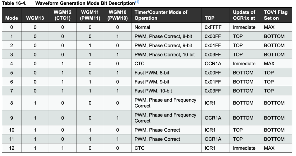
Here the values are given in binary, so they begin with 0b. In TCCR1A you set COM1A1, COM1A0, COM1B, unused, unused, WGM11, WGM10 to 1 or 0. In TCCR1B you set unused (ICNC1), unused (ICES1), unused, WGM13, WGM12, CS12, CS11, CS10, respectively.
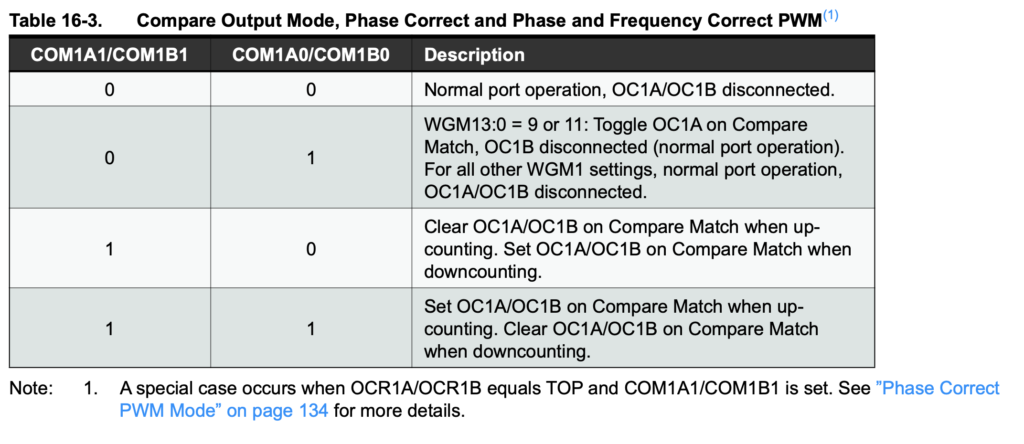
For COM1B1 / COM1B0: 0, 0 means no output; 0, 1 means toggle operation (the output is inverted on a compare match); 1, 0 outputs LOW while the counter is between OCR1A/B and TOP, and HIGH while it is between 0 and OCR1A/B; 1, 1 is the inverse of 1, 0.
Here, since we want to switch the output LED between LOW and HIGH to produce the frequency, we set COM1B1 / COM1B0 to 1, 0.
We choose 1, 0 because it makes the sketch easier to follow.
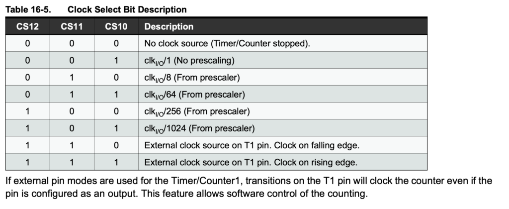
分周比の指定(ATmega328データシートより)
Since we are using a prescaler of 256 here, CS12/CS11/CS10 are set to 1, 0, 0.
To summarize, we get the following.
TCCR1A = 0b00100001;
TCCR1B = 0b00010010;
Next we set OCR1A and OCR1B so that the output is generated with the specified frequency and duty cycle.
PWMPin, i.e. pin 10, is set as OUTPUT, and the frequency and duty cycle are specified with HzWrite(). After waiting with delay(), the output is turned off with digitalWrite(PWMPin, LOW), followed by another delay().
That covers the full program and its explanation.
Afterword
When looking for blog posts on how to change the PWM output frequency, I found many more results by searching for AVR, ATmega328, or 328P than by searching for Arduino.
This post was only a rough overview, so if you want to dig deeper, I encourage you to look into it yourself.
In the program above, the output is toggled between HIGH and LOW. Since delay is specified in milliseconds, delay(1000) waits for one second.
In other words, this program turns the output on and off at 1 Hz.
However, using the delay() function to set the frequency has a number of drawbacks. With this approach, changing the output duration—for example, outputting a 60 Hz signal for five seconds—requires a for loop, which is inconvenient.
That said, because it is so simple, it is a good choice when you just want to try something out.
This function lets you specify the frequency and the duration. So, unlike the delay approach, you can specify the frequency directly without calculating it.
//pinはピン番号
void loop() {
     tone(pin,60);
}
You can write it as tone(pin, frequency) or tone(pin, frequency, duration).
The duration is given in milliseconds, so it is written the same way as delay.
The limitation of this function is that you cannot specify frequencies of 31 Hz or below. In other words, you cannot generate an output such as 1 Hz.
For frequencies above 31 Hz, such as audio tones, it makes specifying the frequency extremely easy, and the code is far shorter and more accurate than using the delay function.
Using PWM output and changing its frequency
Using PWM output offers the greatest flexibility—and it is also why this topic gets so deep.
PWM stands for pulse width modulation. For details, see Wikipedia.
The term alone does not tell you much, but simply put, PWM is a way of modulating an output by changing the duty ratio. The official Arduino explanation is here.
Normally, you would set the brightness of an LED by changing the current. But if the current is fixed and you still want to change the brightness, you can blink the LED at a very high frequency (30–60 Hz is said to be the point where people can no longer perceive the flicker).
Normally the ON and OFF periods are 1:1 (a duty ratio of 50%), but what happens if you make it 4:1 (80% duty) or 1:4 (20% duty)? The former will look bright, and the latter will look dim.
Modulating the output by changing the pulse width in this way is what PWM output is all about.
On the Arduino you can not only generate this output but also change the frequency of the PWM output. The idea here is that by tweaking the register settings—essentially the low-level guts of the Arduino—you can change the PWM output frequency. Incidentally, the default output frequency is 490 Hz, or 980 Hz on some pins.
I will explain how to do this in detail in a future post. Searching for “PWM Arduino frequency change” turns up plenty of explanations.
After reading them about four times, it starts to make sense.
Basically, I suggest looking through these methods to find the one that best fits your own goal.
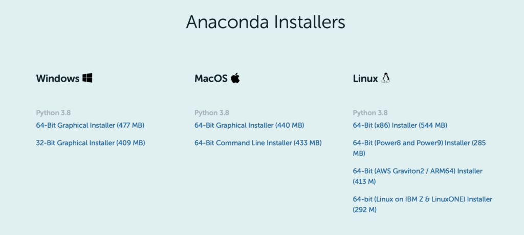
Choose the installer that matches your environment. Since this guide covers macOS, select the 64-bit Graphical Installer.
Launch the installer and follow the instructions to complete the installation.
There are two installers for Mac. The 64-bit Graphical Installer installs Anaconda through a GUI, which is the more familiar approach, and unless you have a specific reason otherwise, this is the one to use.
Downloading the 64-bit Command Line Installer gives you a *.sh file. This is a shell-script installation, used when you want to install from the terminal.
Since installing software on Linux is normally done from the terminal, people used to Linux may find this option easier. (Probably.)
Configuring the command line environment
After installing on macOS, all you get is Anaconda-Navigator in your applications list — as is, you can’t use Anaconda or Python from the terminal.
If you want to use the conda command to install packages and so on, you need to activate Anaconda. To activate Anaconda (i.e., to make the conda command available):
conda activate
Run the above. The conda command should now work.
If activating the conda environment every time is a hassle, you can have it activate automatically. To do so, run the following in the terminal:
~/opt/anaconda3/bin/conda init シェル名
Run the above. Use the name of the shell you actually use. If you have no idea what that means and have never changed it, you’re probably on the default shell (zsh on macOS), so substitute that for the shell name.
~/opt/anaconda3/bin/conda init zsh
Now, when you restart the terminal, the conda environment will be activated automatically and you won’t need to type conda activate.
Many of you have probably heard of GitHub before you ever heard of Git. When looking for a program or a piece of software to use as a reference, you often land on a GitHub page, and I suspect many of you have simply downloaded something without really understanding how the site works.
GitHub is indeed a place where programs are shared, but it is more than just a sharing site: it is a tool for using a tool called Git online.
Git is a tool for version control of files. By modifying files and recording those changes, you can return to any recorded version at any time.
When you ask someone to review a presentation draft, you probably save the file before the review, the reviewed file, and the file you revised based on the comments as separate files. With a tool like Git, you can handle those changes easily, and all within a single file.
A record made with Git, and the act of making that record, is called a “commit”.
The place where commits accumulate is called a “repository”. In other words, a repository is the place that holds the change history. A repository on your own computer is called a “local repository”, while one hosted remotely, such as on GitHub, is called a “remote repository”.
When you want to manage files with Git, you specify the folder that Git will manage. Within that folder there are three areas: the working tree, the staging area, and the Git directory.
The working tree is where your files live, and simply editing a file here does not yet save the change history as a commit.
The staging area is where you register the files to be committed. Files on the stage likewise have not had their change history saved yet; think of it as the place where you declare, “I am going to commit this file.”
The Git directory is where commits are stored. Files committed here are stored as files that will never be altered. In principle, the content recorded by a commit cannot be changed or deleted afterward. Once something is committed to the Git directory, it has been recorded as part of the change history.
Basic use of Git
I will leave the detailed usage for you to look up, but here I give a rough overview of the actual operations.
Git is generally operated using Git Bash on Windows (installed together with Git) and the terminal on macOS and Linux. (Here I will refer to both simply as the terminal.)
There are GUI tools that may feel more familiar, but once you get used to it, using Git from the CUI is extremely convenient, so I recommend starting with the CUI from the beginning. You should get the hang of it within an hour.
First, to start managing files with Git, create a local repository. Begin by moving to the directory you want Git to manage in the terminal. Then,
git init
Entering this gets you ready to use Git for version control.
Next, to record changes in the staging area,
git add ファイルパスもしくはディレクトリパス
Running this registers the specified file in the working tree to the staging area.
Next,
git commit
This commits the files in the working tree.
To check which file is currently in which state,
git status
run this. The commit history can be
git log
checked by running this.
Basically, the workflow is to run git add, then git commit to create a change record, and to use git status to check the current state whenever you run into trouble.
Below is a reference. It is a book that is very easy to follow even for beginners, and I referred to it while writing this article. If you want to study this in more depth, I recommend it.
Extracting one specific value from a pandas DataFrame in Python is surprisingly tricky. DataFrames are designed to be handled as DataFrames, so extracting, slicing, or appending rows is very easy.
When you try to pull out a single value, however, for some reason you don’t get the value itself—you end up with a DataFrame, along with various other issues.
Here I describe how to extract the value in a DataFrame that satisfies a particular condition. There may well be better approaches, but this is the best I can do at the moment.
Suppose we have the DataFrame below and want to extract the value 20 outlined in red.
The problem is that with a simple DataFrame like the one above you can see the index and pull the value out in one step, but with a large dataset it is very hard to check the index number and use it.
With large amounts of data, it is more efficient to extract values using a key column (customer number, id, etc.) as a clue. So let’s try extracting the value in the situation below.
In other words, we want to extract the value in column B for the row where column A is Aichi. This cannot be done in a single step; the value is extracted in two stages.
Errors sometimes come up when you are writing a program in Python. Errors are actually helpful, since they tell you that your program has not been put together correctly, but sometimes an error will stop your program from running altogether.
Sometimes code that is syntactically correct still raises an error at runtime. An error raised when the syntax is grammatically incorrect is called a syntax error, while an error that is grammatically correct but logically wrong is called an exception.
Some examples of exceptions: ・TypeError: the operands are of incompatible types EX. word/2 , 4*number
・ZeroDivisionError: division by zero EX. 3/0
・ValueError: the type is correct but the value is not appropriate EX. int(“string”)
You can use conditional branching to head off errors before they happen and write a logically correct program, but you can also take the approach of handling the exception when an error does occur.
That is the result. Note, however, that except only catches the error you specify (in this program, only ZeroDivisionError), so if any other error occurs it will still be reported as an error when the program runs.
When you expect more than one kind of error, add another “except ErrorName:” clause.
If you leave out the exception name entirely in the except clause, you can catch every exception.
try:
    print(10 / 0)
except:
    print('できませんでした')
Be very careful with this, though: because it catches every exception, it will also hide errors the programmer never anticipated.
There are also keywords related to the try-except syntax that let you specify what happens after an exception occurs. I will list them briefly here. I plan to cover them in detail in another blog post.
raise: deliberately raise an exception
pass: do nothing after the exception occurs
else: run only if no exception occurred
finally: always run, whether or not an exception occurred
Arduino is controlled using the Arduino language. Sooner or later, however, you will want to do something more complex, or to control an Arduino together with another program.
The module introduced here, pySerial, lets you carry out serial communication with a Raspberry Pi or an Arduino. Through serial communication, you can send commands from a Python program to an Arduino or Raspberry Pi and control them from Python.
Here I introduce the basic program for doing this. Just being able to use it will greatly expand what you can do with your programs.
Installation
pip install pyserial
You can install it by opening Python in a terminal or command prompt. Alternatively, you can install it from a terminal in an IDE such as PyCharm.
Example program
This example turns an LED on and off at one-second intervals. I will test it by driving pin 13, which is connected to the LED built into the Arduino. The Python program looks like this:
import serial, time

def main():
    #  COMポートを開く
    print("Open Port")
    ser = serial.Serial("COM3", 9600)
    while True:
        #  LED点灯
        ser.write(b"1")
        time.sleep(1)
        #  LED消灯
        ser.write(b"0")
        time.sleep(1)

    print("Close Port")
    ser.close()

if __name__ == '__main__':
    main()
Use serial.Serial to specify the port and the serial communication settings. For the Arduino UNO, specify 9600. This differs from board to board, so check it in the Arduino IDE.
The b in b”1″ plays a crucial role. With the serial.write() function, numbers and strings must be converted to byte sequences before they can be sent over serial communication. The b prefix is needed to indicate that the value is a byte sequence.
Since this program is an infinite loop, the LED keeps switching on and off every second until you stop the program.
Here I use a switch-case statement. It makes the program easier to follow. For details, take a look at my previous blog post.
In this program, sending 0 sets the pin LOW and sending 1 sets it HIGH. Using this program as a base, you can control an Arduino from a Python program in all sorts of ways.
![My elif conditional branching isn’t working!! [Python]](https://www.tankobucreate.com/wp-content/uploads/2021/06/python_cover.png)
![Changing Pulse Wave Frequency and Duty Cycle Using PWM Output [Arduino UNO]](https://www.tankobucreate.com/wp-content/uploads/2021/04/eyecatch-arduino-2.png)